Sunday, June 5, 2016

Arduino For Beginner - Week 3 lesson 2 - Piezo and Speaker

This exercise will teach you about how you can use the Photo resistor and Piezo or Speaker to make a noise or sound.

Schematic
You can download the schematic and also the code from This link 

Arduino For Beginner - Week 3 Lesson 1 - Servo and Potentiometer

This part you will be able to learn about how you can use the Servo with Potentiometer using Arduino UNO.

Schematic
  You can download the schematic and also the code from This link 

Arduino for Beginner - Week 2 Lesson 1 - Temperature Sensor

Today you will learn and get to know a sensor called TMP 36GZ that it used to retrieve the temperature of a place that it sit with Arduino UNO and LEDs

Schematic


You can download the schematic and also the code from This link  

Arduino for Beginner - Week 2 Lesson 2 - Photo Resistance

This lesson will help you to see more about 3 Photo Resistors working differently and control the LED lightness.

This Link
Schematic


 You can download the schematic and also the code from This link

Sunday, May 29, 2016

Arduino for Beginner - Week1 Lesson2 - Series of Light On

This tutorial will help you to make a series of light will turn on each time in series with a simple push button.
You can download the schematic and also the code from this link  

Arduino for Beginner - Week 1 Lesson 1 - Simple Circuit

This lesson will teach you how you can just build a simple circuit with Arduino, LED and a push button. You will also see the tutorial on my video.

Arduino for Beginner - Arduino Board

I will show you the description of all pins on the Arduino Board so you can see how it work and use it at the right way.

Arduino for Beginner - Introduction to IDE

You will learn about the IDE and program to use for Arduino development or projects such as Arduino IDE and fritzing.

Arduino for Beginner - Electronic Symbol


This video will handle the common symbol those are used in the course of Arduino for Beginner so you can see and understand when you see them in the schematic circuit.

Tuesday, May 3, 2016

Business card design and mockup

Today I just want to show you a quick tip about designing a business card mockup so you can easily show it to your customer about the way it look in real life and they can feel that it is modern and like it. I used Adobe Photoshop to do this so I would recommended you to use Adobe Photoshop any version from CS2 up to CC.
For this tutorial section I used Adobe Photoshop CS5 so it works nice and fast enough for my computer.

So  get in to the tutorial now:


How to Share With Just Friends
How to share with just friends.
Posted by Facebook on Freitag, 5. Dezember 2014

Sunday, May 1, 2016

Smart LED WB2812b

How it work
This LED is very special because it can change the color up to three colors(Red, Green and Blue) range from 0-255 on each color.

Circuit
VDD = Voltage in (3.5v - 5.3v)
DOUT = Data Output
DIN = Data Input
VSS = Ground

Arduino Chapter 1 - LED fade

How it work
This example will guide you to make a fade on LED using Arduino IDE. As the previous lesson you saw how you can bright an LED up and turn it back off and now I am going to show you about you can make it fade ON and fade OFF. 

Requirements
- Arduino board
- Breadboard
- hook-up wires
- LED 3v
- 220 Ohms or 250 Ohms resister

Code
int led = 9; // the PWM pin the LED is attached to
int brightness = 0; // how bright the LED is
int fadeAmount = 5; // how many points to fade the LED by

// the setup routine runs once when you press reset:
void setup() {
// declare pin 9 to be an output:
pinMode(led, OUTPUT);
}


// the loop routine runs over and over again forever:
void loop() {
// set the brightness of pin 9:
analogWrite(led, brightness);
// change the brightness for next time through the loop:
brightness = brightness + fadeAmount;
// reverse the direction of the fading at the ends of the fade:
if (brightness == 0 || brightness == 255) {
fadeAmount = -fadeAmount ;

}
// wait for 30 milliseconds to see the dimming effect
delay(30);
}

Arduino Chapter 1 - Digital Read Serial

How it work
This example will show you how to tract and display the switch state. It will show you when the switch is pressed and released.

Requirement

- Arduino or Genuino Board
- A momentary switch, button, toggle switch or switch button
- 10k ohm resistor
- hook-up wires
- breadboard


Cuircuit

Code
// digital pin 2 has a pushbutton attached to it. Give it a name:
int pushButton = 2;
// the setup routine runs once when you press reset:


void setup() {

// initialize serial communication at 9600 bits per second:
Serial.begin(9600);
// make the pushbutton's pin an input:
pinMode(pushButton, INPUT);
}


// the loop routine runs over and over again forever:
void loop() {

// read the input pin:
int buttonState = digitalRead(pushButton);
// print out the state of the button:
Serial.println(buttonState);
delay(1); // delay in between reads for stability
}


Saturday, April 30, 2016

Photoresistor

How it works
This sensor can be called light-dependent resistor, LDR, or photocell is a light-controlled variable resistor. The resistance of a photoresistor decreases with increasing incident light intensity.

Circuit:


Reflective Optical Sensor TCTR5000

How it works
This sensor is reflective with infrared light and it contained emitter and phototransistor in a leaded package. This sensor will send the signal HIGH(1024) when it sees light color or reflection and it will produce down to LOW(0) when it sees darkest. So we can use that range for many different tasks depending on the project.
Circuit:
This sensor has for legs which we have to be careful when we attach it. The image below will help you to see and understand which leg should be working the right way. Please see the image below: 


IR Receiver Modules TSOP382, TSOP384

This sensor is used to receive the signal from remote control using infrared red.
It will help you to communicate between the Arduino and your electronic components remotely with any remote control.
Specifications:
This sensor has three legs and they are doing differences job
1 = Output signal which used to send the signal that it gets from remote control to the Arduino
2 = Is ground
3 = Input voltage which range from 2.5v - 5.5v

Ultrasonic Ranging Module HC - SR04

This sensor is used to determine the non-contract distance between 2cm-400cm function.
We can use it tell the distance and to do something in that distance as well. 
Specifications:
This sensor has four legs such as 
- VCC = input voltage range from 2v to 5.5v
- TRIG = Trigger it used to send the sound out 
- ECHO = it used to calculate the waiting time when the sound from trigger is returning back
- GND = is ground 

Arduino Chapter 1 - LED Blinks

This sample is the very basic sample and a basic start for beginner.
Working with led and Arduino to control the way it turns ON(HIGH), OFF(LOW) and Blink.

Requirement
- Genuino/Arduino Board
- 1 LED 3v
- 220Ω resister

Circuit:

Code:
void setup() {
// usedigital pin 13 as an output.
pinMode(13, OUTPUT);
}
// the loop function runs over and over again forever
void loop() {
digitalWrite(13, HIGH); // turn the LED on (HIGH is the voltage level)
delay(2500); // wait for a second

digitalWrite(13, LOW); // turn the LED off by making the voltage LOW
delay(2500); // wait for a second
}

Arduino Chapter 1 - Read Analog from Serial device

This example will show you how does a serial device send signal to Arduino and how Arduino will track those signal then show it on the screen through Serial Monitor of Arduino IDE.

Requirements:
- Arduino or Genuino Board
- TCTR 5000 Sensor

Circuit:


Code:
void setup() {
// initialize serial communication at 9600 bits per second:
Serial.begin(9600);
}

// the loop routine runs over and over again forever:
void loop() {
// read the input on analog pin A0:
int sensorValue = analogRead(A0);
// print out the value you read:
Serial.println(sensorValue);
delay(1); // delay in between reads for stability
}


Arduino Chapter 1 - language structure - setup() and loop()

In Arduino they use their programming language which is using OOP but they have customize some keywords or namespaces.

Today I am going to show you about the base structure of Arduino such as Setup() and Loop()


setup()This function is called when a sketch starts. Use it to initialize variables, pin modes, start using libraries, etc. The setup function will only run once, after each powerup or reset of the Arduino board.

Example
int btnPin = 3;
void setup()
{
  Serial.begin(9600);
  pinMode(btnPin, INPUT);
}

void loop()
{
  // ...
}

Note
Serial.begin() //used to tell the processing speed be tween Arduino and computer
pinMode(pin,status) //used to assign status to a pin

loop()This function is used to loop the action repeatedly again and again.

Example
void loop()
{
  if (digitalRead(buttonPin) == HIGH)
    Serial.write('HIGH');
  else
    Serial.write('LOW');

  delay(1000);
}

Note
digitalRead() //used to read digital signal from a pin
Serial.write() //used to show the information back to the computer through Arduino


Friday, April 29, 2016

Vongchann Electronic Arduino with OLED Display Screen


Wooo. OLED.
Do you know what is OLED stand for? it stands for Organic Light Emitting Diots. Today I am gonna show you how this thing will work with Arduino and You will also see that what can OLED do or show on its screen.
I am using 128x64 pixels OLED so it is quite small but it works well.
Before you can start working with this OLED and Arduino the main thing you have to know is the serial and ID of it as the OLED that I am using is U8GLIB_SSD1306_128X64 u8g(U8G_I2C_OPT_NONE|U8G_I2C_OPT_DEV_0);
This article just want to show you about how I test it, if you want to see more about the tutorial of the process and how you can work with it step by step, then just calm down and follow or subscribe my channel.

Now. let's see my video about using Arduino with OLED Display Screen

Vongchann Electronic - Arduino with HC SR04 Sensor test


Today I have another sensor called HC SR04. This sensor used to tell the distance between object that is right in front of it. This sensor has two special parts that we should never forget such as:
Trigger: is the part which send out the sound to hit any object in front of it
Echo: is the part which wait for the sound to come back and calculate the waiting time
According to these two parts this sensor can help use to find the distance between object that is in front of it.

In fact, Want to see how it works? Watch the video below then you will see it.

Vongchann Electronic - Arduino And Remote Control Test


Now it is time for you guys to see my experiment with Arduino and other electronic component and now I choose IR Receiver to make a remote control with LEDs.


When I press the button on the remote control it will tell the LED which I assigned to turn on then I press another button it do the same way and I can also turn them off with the remote control as well. The interesting thing about this experiment is I will change various of remote control so you can see that we can use Arduino to manage and control those components.
Check my video below you will see how it works.

Vongchann Electronic - Electronic Circuit


After we have known and understand how Ohm Law works; now I would like to bring you guys back to see about electronic circuit which we have already learned at high school.
In this article I just want you guys to see the differences between two electronic circuit such as Serial and Parallel.
Serial: The circuit will focus on the voltage of each electronic component and they will continue adding the voltage of all the components to the circuit.
Parallel: The circuit will focus on the current that flow a long; it doesn't care about huge voltage but it cares about the current that it would be able to handle the electronic components.
See my video you will see and understand more about these two types to circuit:

Vongchann Electronic - Ohm Law


I want to have a bit of review about Ohm Law before we jump in to the lesson about electronic, it is really useful in physic theory that Ohm Law is used to describe about the potential difference (voltage) across an ideal conductor is proportional to the current through it. The constant of proportionality is called the "resistance", R.Ohm's Law is given by:
V = I R where V is the potential difference between two points which include a resistance R.
As this is the matter for all learners I would like you guys to see my video about Ohm Law as shown below:

Arduino Board Introduction about each pins, ports and its functionality


I will show you more about the Arduino or Genuino Board. This lesson will help you to understand how each pins work and see how it looks.

Here is the technical specifications about the Arduino UNO board will have 
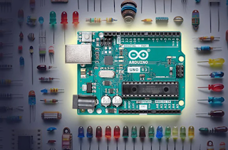
Operating : Voltage 5V
Input Voltage (recommended): 7-12V
Input Voltage (limit):  6-20V
Here is the pins and the numbers of each categories
Digital I/O Pins 14 (of which 6 provide PWM output)
PWM Digital I/O Pins 6
Analog Input Pins 6

Want to see more about the descriptions and definition of each pins and ports check my video below:

First Start and Requirements for Arduino Project Experiment


To start with Arduino Development and Experiment you will need to have some devices and program set up ready.
Devices: Arduino/Genuino UNO or Arduino MEGA or any Arduino
Programs: Arduino IDE/Arduino Work Station and Fritzing
In order to help you to understand the requirements I would like to share to you with my video clip about those.

Visitors